How to Calculate Capacitance and Identify Capacitors
Types of Capacitors:
Types of Capacitors:
In my last article on Capacitor and its applications, I needed include the discussion on how to identify a Capacitor and how to calculate its capacitance for any electronics circuit project.
Capacitor
Capacitor as I discussed in my last article is a two terminal device with a di-electric in-between them serving as an insulator. These insulating medium could be a paste of electrolyte (electrolytic capacitors), paper or even air.

Electrolytic capacitors
are easily identifiable as its ratings (voltage rating and capacitance value) are all written boldly on it. The voltage rating of a capacitor is also known as the maximum voltage or the voltage capability of that capacitor that it can withstand without been damaged (burst, explode or even bridge the entire circuitry).Also, electrolytic capacitors are known to be such as they have polarity (as in positive and negative terminal). For you to be able to identify the polarity of an electrolytic capacitor, just look at its side, you will notice a demarcated strip of line, sometimes; it could be a broken continuous strip of line. That portion of the terminal is the negative terminal. Because that strip by it denotes the position of the negative terminal of the capacitor. This means that, the other terminal that is left uniformly colored with the rest side of the capacitor is the positive terminal of the capacitor.

Electrolytic capacitors are usually in micro-farad (µF) ranging from low values as 0.01µF to 10,000µF as commonly available in the markets. These types of capacitors do not need calculating their capacitance anymore since it is already indicated by the manufacturer. All you need to know and be concern with is its application. What do you want to do with it and where to insert it on your Printed Circuit Board or Veroboard. Below shows picture of an electrolytic capacitor as commonly available in the market.


Ceramic Capacitor:
Ceramic capacitors are other type of capacitor that has smaller values compared to electrolytic capacitor. These types of capacitors are mostly applied in areas of high frequencies such as in radio frequency applications. They are easily recognized by the digit of number and alphabet written on them as also a variable resistor.
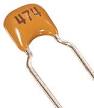
Usually or commonly, you could see something of this sort: 103. This means that the value of the capacitor is 10nF (Nano-farad). The last digit “3” is the multiplier. Also, sometimes you could see something like 103k. This means it is 10pF (10 Pico-farad) where the “k” denotes a multiplier of 10^3.
But also, you could find just “10” written on it meaning its 10pF. Below is a picture of how a
ceramic capacitor
looks like.

What are your intentions? What do you want to use the capacitor for? All these determine the kind of capacitor to use and not to use. For instance, in building power supply unit for a device that uses a 12v DC or requires a 12v DC output, you MUST not use a capacitor rated at 5V. This will cause the capacitor to overheat and burst or cause a short circuit on your board. This means that you have exceeded the maximum rating of such capacitor specified by the manufacturer.

It is highly recommended to KNOW what type of capacitor you really need at a time and its power requirement needed to withstand your demand. For a 12v supply, I advice you use a capacitor rated at 15v to 18v working voltage (WV).
No comments:
Post a Comment
We Love comment(s) or question(s). Please feel free and hit us!