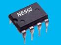
555 TIMER AND CIRCUIT APPLICATIONS (NE555, LM555)
555 Timer Integrated Circuit are commonly use in L.E.D Sequencer, Clock Generator also known as Oscillator and in basic electronics practice. They are usually known as Timer I.C; sometimes hobbyist calls it 555 Timer.
555 Timer are widely use in the field of electronics such as in Laptops, TV, and Timer Circuits (Bomb Trigger Circuit) and so on. In Digital Clocks, Indicators requiring flashing operations, in L.E.D Sequencer use in Christmas displays and lots more down to complex applications in electronics design.
Today, I shall only introduce you to basic applications of Timer Integrated Circuit and configurations (Ways of Application).

AS A MONOSTABLE
555 Timer can be connected to operate as a Monostable Flip-flop. As the name implies, it is a multivibrator that has only one (mono) stable state. That is to say, when it is been triggered whether intentional or unintentionally, it changes its state (output) and then later returns back to its original state where it was before it was triggered. In a way, its like saying when a monostable timer is triggered, its output changes state from Low (0) to High (1) where the Low represents the absence of a voltage or signal and the High represents the presence of a voltage or signal.

Below is a way to connect the terminals of a 555 Timer to operate or function as a Monostable flip-flop. Its pin 2 is the trigger pin, pin 3 remains the output pin, pin 6 is connected to pin 7 and a frequency determining network (RC Network) is connected between pin 7 and Vcc (Power supply line) and the Ground (0v). Remember that pin 4 and pin 8 is always connected to the supply rail (Power supply line) and pin 1 is always connected to Ground (0v).

The output of this circuit can be connected to drive a Relay, an L.E.D, and a Buzzer and so on. Note the Trigger pin (pin 2) must not or is not advisable to be left floating (unconnected) so as not to be falsely triggered by stray alternating signals around, even from your hands close to the trigger pin can cause it to be triggered. Therefore, you could connect a load resistor between pin 2 and supply rail, then having a pull0down switch from pin 2 to ground. This keeps the input of the Timer High, until when pulled down to 0v (Ground) by the switch before it triggers the circuit.
AS AN ASTABLE MULTIVIBRATOR (OSCILLATOR OR CLOCK GENERATOR)
A 555 Timer connected as an oscillator or astable multivibrator operates on a free-run ground. What I meant is, it does not require your effort to cause it to oscillate (or trigger unlike a Monostable). Once the power source is powered ON, it begins to oscillate (ON and OFF alternatively and continuously) except the power source is disconnected or switch-Off.

There are cases we need this kind of operation. In events or situation where we need a clock pulse (oscillation) to be triggering our circuit independently and continuously, we then apply a 555 Timer connected as an oscillator. Please note that the waveform (wave shape) produce by a 555 Timer is a pulsing or square like waveform. This MUST not be mistaken or assumed to be a Sine Wave!
Below is a practical oscillator circuit with actual values that you can experiment with.

In 555 Timer been use as an oscillator, pin 2 is connected with pin 6, pin 4 and pin 8 is connected to the supply rail as usual as seen in the above diagram. Pin 1 is connected to 0V (Ground), Pin 3 is our Output terminal. A capacitor (say C) is connected between Pin 6 (along side pin 2) and Ground. A resistor (say R2) is connected between pin 6 and pin 7, another resistor (say R1) is connected between pin 7 and supply rail (or pin 8 and pin 4 since they both are also connected to the supply rail). The output been pin 3 could be connected to drive any load say a Relay that could in turn operate a contact to switch ON a Motor, Fan, Conveyor, Lamp, L.E.D and so on. Below shows a practical configuration and values of component use in constructing an oscillating circuit.
Ping me a mail if you have any question or assistance regarding the discussion above. I shall be there to attend to you ASAP!
Thanks for taking time to read! You are wonderful! Let’s make it a date again tomorrow, as I hope to furnish you with another interesting package. Don’t miss it!
Isaac Johnson
Circuit Design And Technology